Friday, July 5, 2013
Autodesk AutoCAD Civil 3D 2014 Hotfix 1
Autodesk has released Hotfix 1 for Autodesk AutoCAD Civil 3D 2014 which addresses a number of various issues found by customers and Autodesk. As always, you should take a look at the read me file prior to installation. It is important to note, that this Hotfix can be uninstalled from the control panel.

Thursday, June 20, 2013
BIM Specialist Certification
Autodesk has announced a new certification program that is based on a workflow. The certification is called Roads and Highways Workflows using the 2014 Infrastructure Design suite. Autodesk has been certifying users on individual products for quite some time, but this is something new. The exam itself is broken down into the following topics:
- Project Planning
- Preliminary Design
- Detailed Design
- Visual Communication
- Create a storyboard
- Select a road style
- Create a proposal
- Import the .imx file into Civil 3D
- Create the initial corridor
- Preform clash detection
- Calculate cut/fill
- Render Images
Here is where you can find a complete list of objectives for the exam. The exam will focus on such programs as Civil 3D, Navisworks, 3Ds Max and various other products.
A book has been created by Ascent which matches the name of the certification and can be used for preparing for the exam. Information for taking an exam at one of our facilities can be found at the following Advanced Solutions link.
Monday, June 3, 2013
Shared Reference Point Tool
On the Autodesk Subscription Site, under the productivity tools for AutoCAD Civil 3D 2014, you will find the Shared Reference Point Tool. There is an installer for Civil 3D, which runs from the Toolbox, and then a second installer to run on Revit.


The extension exports an XML from Civil 3D with X,Y, and Z coordinates, along with the corresponding rotation and units. This reference point defines the relationship between the site and building.
GEOREMOVE Command
As many of you are using the GEOMAP command, it has come to my attention that several users have tried to use this command, only to have an Aerial photograph inserted in an incorrect location. This seems to happen with existing older jobs that were created in prior versions of Civil 3D. In order to get around this issue, I have had the users with this issue simply type the GEOREMOVE command, which clears the current coordinate system from the drawing. After the coordinate system has been set to No Datum, No projection, simply go and re-assign the proper coordinate system, and the Aerial photograph should come in the proper location.
Tuesday, April 9, 2013
Live Map Service - Civil 3D 2014
In Civil 3D 2014, Autodesk has introduced a live map service to acquire satellite images. In order to to use this service, the user first needs to log into Autodesk 360, and have a coordinate system assigned to the drawing. After logging in, the user simply needs to type GEOMAP on the command line.


The user is presented with several choices. The first choice is Aerial.

The second choice is Road.

The third choice is Hybrid. This is a combination of Aerial and Road.

Lastly, the user can simply select off to hide the imagery.
Thursday, April 4, 2013
AutoCAD Civil 3D 2014 - New Features
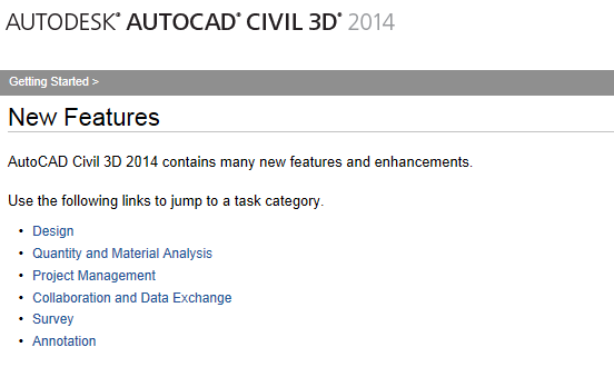
As you probably know by now, AutoCAD Civil 3D 2014 has been released to the masses. I will try to summarize the list of new features that have been added or enhanced in this years version. A good place to start as always is the help files.


- Pressure Pipe Enhancements
- Create Network from Objects
- Can be added to cross section views
- Can have assigned pay items in the Parts List
- Can be used via the data shortcut
- Sort parts lists by size
- New annotation options
- Can be added to plan production sheets
- Extract Corridor Solids
- Data references are saved in the drawing
- Improved interoperability with InfraWorks (Otherwise known as AIM)
- Survey Queries Import and Export
One of the more interesting features in Civil 3D 2014 is its backward compatibility with Civil 3D 2013. This means that 2014 files can be opened and edited in 2013. However, there are some limitations due to enhancements in 2014. The screen capture below talks about the limitations. This can also be found in the following link Round-Tripping Data between versions.

Lastly, here is the new logo for Autodesk going forward.
Monday, March 18, 2013
Geotechnical Module for Civil 3D
Roughly a month ago, Autodesk released the Geotechnical module for subscription customers. It can be found under the Productivity Tools for AutoCAD Civil 3D 2013.


It is important to note that installation of SQL server as well. After installing the module, you will see the following addition to the ribbon.

To begin the process of importing soil boring data, we will select import. Before we can import any boring data, a drawing will need to exist, which means it must be saved.

The import data box allows us to select the appropriate files to be imported. I'm bringing in data via csv. There are also options to import data via AGS 4 and AGS 3.1. Here is a link to AGS that discuses in further detail the formatting and group headings. Since I have chosen a csv file type, I will be importing to files HOLE.csv and GEOL.csv. It is important to note that in this version of the module, the csv files must be named exactly as I stated, including case sensitivity. Samples of these files can be found at Keynetix, along with sample tutorials for using this module.

After selecting import, your boring data will be brought into your drawing. As you can see from the screen capture, the borings are brought in with an x,y, and z location. Note in the view on the right, the borings are broken down into various stratum.

From the Borehole Manager tab, when can select which borings we will like to include, along with assigning an appropriate style for the type of boring as seen below.

From the Strata Manager, we can select which surfaces we would like the module to create within Civil 3D.

The Hatch Manager allows the user to assign various colors and hatch patterns to an array of soil boring materials.

Finally, the Create options allows the user to add the soil borings to profile view for a given alignment.

The borehole selection screen allows the user to choose which borings will be added to the profile view.

Now simply select create, and the soil boring data is added to the profile view.


Subscribe to:
Posts (Atom)