Monday, May 14, 2012

Share coordinate systems between AutoCAD Civil 3D and Revit


Autodesk Labs has come up with a BIM  tool for assisting in the sharing of data between Civil and Architectural world.


 The tool specifies one common XYZ point and its orientation in the XY plane between the two coordinate systems. This reference point defines the relationship between the building and site grid.


After downloading the installer, you will see that Shared Coordinate component has been added to the toolbox.


Upon executing the utility, you will be asked to select the origin point of the building or structure.


You will also be asked to select a second point on the same structure.  This second point allows for the rotation.


You will be given the option of determining the drawing units.


Finally, you will save the coordinate system file that you can send to your counterpart on the Revit side.  This will allow you both to keep your data in the proper location at all times.


Wednesday, May 9, 2012

May the "Force"main be with You


One of the major new features in Civil 3D 2013 is the addition of pressure pipe.  The tools provided now give some new methods for laying out pressure pipe such as water main.

As you can see above, pressure networks have their own place to reside on toolspace.  


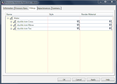
There are also pressure network part list similar to the one seen above.  In these parts list, there will be pipes with appropriate sizes and materials similar to what we would be expected from previous sanitary and storm parts lists.  These new parts lists will also include fittings such as tees, elbows, and crosses.  Under appurtenances, such items as gate valves will be available.  Upon creating a pressure network, you see the following options available on the ribbon.


After choosing the appropriate size, material, and depth, you can proceed to start laying out pipe.  

Notice the yellow circle and ticks as pipe creation is taking place.  The tick marks represent various angles for predefined elbows that are available to use. 

As you can see, there is no a parametric part that represent the fitting.  It is worth noting, the arrow grips allow us to flip the fitting, the diamond grip allows us to pull the pipe, and the rectangular grip allows us to change the location of said fitting.

Besides creating and editing pipes in plan view, the preview above shows how we can edit in profile view as well.  The following shows the curve pipe option.


The follow surface option is displayed below. 


As you can see from the information I have included, Autodesk has provided another great tool within the Civil 3D arsenal for designing pressure pipe.