Friday, December 23, 2011

Project Silverstar

Autodesk Labs has come up with a preview technology called Project Silverstar.  Silverstar uses optimization techniques to design a layout or finished ground  profile with respect to earthwork costs.


Upon downloading the application, it will be added to the toolbox under Technology previews.


Upon executing profile optimization, you will be asked to log into your individual Autodesk account.  The reason for the log in is to email you the solution that is being derived by the application.


After logging in, you will then be prompted to select the appropriate alignment that you would like a profile designed for.  Notice in the upper right the email address, this is why the log in information is requested from the previous screen capture.


You will also be given access to a cost table to assign appropriate costs associated with earthwork.


Once you select the appropriate alignment and corresponding surface, you will proceed to the borrow/waste option.  This is where we can define station to include a borrow or dump location similar to that of a Mass Haul diagram. 


The next screen allows the user to define minimum and maximum grades that will be permitted, along with allowable tangent lengths.


Finally, the optimization table allows the user to control the intensity of PVI's, along with solution precision and time.  It should be noted that the more profile options selected and other precisions chosen will determine the time frame to process the profile and email an optimization profile.


After finishing the wizard, you will then be sent an email containing the following information.


The pdf report will contain the optimization determined by Silverstar from the information provided as seen below.


Finally, the text and xml provided can be used in Civil 3D to generate the profile created in the optimization report.

Thursday, December 1, 2011

Corridor Solids

Autodesk Labs has come out with an extension for creating corridor solids from Civil 3D subassemblies.  The extension allows for creating solids that can be used for better visual renderings, class detection, and coordination between various team members using various Autodesk applications.


After downloading the extension, you will see that it has been added to the Toolbox residing on Toolspace.


Upon executing the command, you will get the following pop up box.


The options in the box are simple to follow. We simply need to select the corridor we wish to generate solids for.  We can also assign layers to our subassembly shapes.


The final box allows us to generate the solids in our current drawing or in a new one.


Here is the output generate by the extension in plan view.


Finally in plan view.  Now it is available for a variety of uses.

Friday, August 5, 2011

Caice Extension for Civil 3D 2012

For those of you who use Caice or have data in a Caice format, Autodesk has created an extension for bringing Caice data into AutoCAD Civil 3D 2012.  The following is from the support - utilities and drivers section of Civil 3D on the  Autodesk website  As always, be sure to download the proper version for your operating system.


Upon installing the extension, you will get some additional Caice tools added on the Toolbox tab of Prospector as seen below.


Wednesday, July 27, 2011

Civil 3D 2012 Bid Express Extension

Autodesk has released a new extension for those users who do work for a department of transportation.  The bid express extension allows us to use the functionality of QTO and ultimately tie it to pricing and establish cost estimations. 

Once you have downloaded and installed the proper executable file, you will see the following  options listed under miscellaneous utilities on the Toolbox tab.


The first option under the extension is subscribing to a web service.  The first thing I will mention about this is that you only need to sign up to get access to the pay item and report pricing with an email address and password.  Currently the service is being provided to users at no cost, even though it asks for billing information when continuing with an activation email.


Upon setting up your account, you will then select get pay items and execute where you will enter your user name a password.


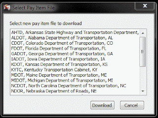
After logging into Info Tech's service, you will be presented with a list of pay item files available for download, similar to the one seen below.


Once you have selected the appropriate pay item file, you can then use QTO to assign the pay items to your Civil 3D and AutoCAD objects as needed.  Finally, when you are read to generate a takeoff report, you will select the produce price report.


Give the appropriate name for you bid report and select go.


Notice that your report is taking form, but you must select get price report to finish it.  You will most likely need to log in again to the get the price to update as seen below.


Finally, we can either create a report or have it create a table in Civil 3D.


Tuesday, July 19, 2011

Creating a Box Around Structure Labels

Today I was asked by a client if there was a way to show a box around all of the  structure information in plan and profile view as seen below. 


In the label style composer, you can turn on a box for a given component, but there is no simple way of turning on or off a box that encompasses all of your structure information.  The reason that we can't make one label is because of the text for each component that has to be added to generate invert information.  The approach that I took to create the above label was to add the structure name component to the top and bottom of the label, with the bottom copy display set to false.  I then attached a line component to the top of both of the structure name components in the top left and top right to get the proper length of the line.   This generates the top and bottom of the box.


As shown above, I finally create the box by adding two more line components.  Line 3 is determined by selecting the start anchor point to be the start of line 1and the end anchor point is set to the start of line 2.  Conversely, line 4 is created by doing the same process except choosing the anchor point to be the ends of lines 1 and 2 respectively.   We have essentially created a box from four lines.  The one caveat that we must take into consideration, is if the invert information is longer than that of the structure information, we will have text outside of the box since the lengths of lines  1 and 2 are determined by the structure name length.

Thursday, July 14, 2011

Creating Point Styles with 3D Blocks

I have been recently working with a energy consultant who is looking to use point styles for visualization purposes.  I had previously showed them how to use Google Earth along with other Civil 3D tools to send the client a kmz file to give a good perspective of the impact on surrounding neighbors.  I would suspect that many of you have tried to do this and eventually gave up.  The key to using a mvblock as a point marker is to completely purge the block from the drawing.  For some unknown reason, the mvblock must not reside within said drawing.


As you can see from the screen capture above, you must browse to the location were the mv block resides.  The default location of the multiview blocks for Civil 3D 2012 is C:\Program Data\Autodesk\C3D 2012\enu\Data\Symbols\Mvblocks.


Finally, here is what the point style looks like in 3D.


Lastly, make sure that your point style has the marker turned on in the model view direction.


Friday, July 8, 2011

QTO - What is What?

Recently I was asked some general comments about QTO, so I felt this was a good topic to discuss. Below are the questions I was asked:


1.  What items can you assign pay items to?  Besides assigning payitems to pipe networks and code sets for example, you can also assign to polylines, blocks and text.  I like to assign a driveway demolition payitem to asphalt removal text so I can track the number of driveways to reconstruct.


2.  What happens to an object like a polyline if you break it into more than one piece?  The payitem is assigned to both pieces and would and the report would still show the proper quantity.

3.  Can you assign more than one payitem at a time to a given object?  Hitting control and selecting the appropriate payitems will allow you to assign the appropriate amount to a given object.  A good example would be areas that will need seeding, mulching, and stabilizing.


4.  Can we have a payitem calculate the area for example in some other type of measure than what is in the payitem file?  The formula option within each payitem row allows for other calculations to take place such as cubic yards instead as oposed to cubic feet.


Wednesday, July 6, 2011

Update 2 For Civil 3D 2011


Late last week, Autodesk released AutoCAD Civil 3D 2011 Update 2.  This update addresses several issues that Autodesk and customers have encountered.  It is important to note that AutoCAD Civil 3D 2011 Update 1 must be installed prior to installing Update 2.  As usual with other updates and hot fixes, please install the proper version of your install ( 32bit or 64bit).  For a list of items addressed, you can look in the readme file.

Tuesday, June 28, 2011

Changing Your View in 2012

One of the first things you will notice when you start Civil 3D 2012, is the new view options you will see in the top left of model space as seen in the screen capture below.


The first option we will look at is [-] or the viewport option.  As seen in the capture below, this option allows us to control the number of viewports being displayed and there configuration.  It also allows for the display of the tools such as the viewcube and navigation bar.


The second option we will look at is view.  This gives us the option of setting the perspective of the current view.  In the example below, the current view is set to top.


The third option we will look at is view style.  This gives us the option of setting what visual styles we are currently displaying.  Notice that along with the visual styles, the manager is available to make modifications to the styles on the fly.


Finally, if you choose to get to these options through more traditional ways, such as the view menu or ribbon, you can turn off the viewport control options on the 3D modeling tab as seen below.


The use of this new tool should allow for time savings when switching between various views styles and perspectives all from a single location.

Monday, June 20, 2011

Google Earth and Civil 3D

This is a topic that has been covered numerous times, but I have been asked several times in the past two weeks.  It seems that a few of you are having issues bringing in a surface from Google Earth.  As many of you have seen in the past when bringing in Google Earth surface, it tends to get stuck importing around 49 or 50%.  In newer builds of Google Earth, the amount of points that could be imported as gone from 10,000 down to 5,000.  In order to remedy the situation, we need to look at the two command settings of ImportGEdata and ImportGEsurface under surfaces.


Upon editing each of the commands, you will see Google Earth rows and columns.  As the screen capture below depicts below, we need to change both values to 70.  The value of 70 is arrived at because 70 times 70 is 4900, and 5000 point are allowed.


By making the row and column change in both command settings, the GE surface should import into our drawings as expected.


Thursday, June 16, 2011

Controlling the Contour Label Line

During a Civil 3D essentials class this week, a CAD manager asked what was the best way to control the label line that is attached to the contour label themselves. 


As seen in the screen capture above, the line is useful when trying to decide where to put the labels themselves, but obviously we don't want to show the line when we are ready to plot are sheets.  In order to control the label line, we ultimately have two options.  The first option I will discuss is using the properties box.


Notice in the capture above, the second option that says display contour label line.  By selecting false, this will turn the line off.  Also, don't forget to use the select similar option, this will minimize having  to do this process more than once or twice.  The second option, which I prefer is to set the template to have them turned off prior to labeling the contours.


As the capture above shows, by selecting the surface feature settings, you can control the whether or not the line is ever going to be displayed in the drawing before a label is even placed.


Wednesday, May 25, 2011

More New Features in Civil 3D 2012

In some of my previous blogs, I talked about a handful of new features to take advantage of in the 2012 product.  Today, I would like to talk about three additional tools that at your disposal.

The first tool I will talk about is creating cross sections that can sample multiple corridors at the same time.  In the past this wasn't possible because the corridor was ultimately tied to the alignment and corresponding sample line group.  As you can see in the screen capture below, you can now have more than one corridor selected when sampling sources.


The second tool I will talk about is tangency check.  Like other design checks that are currently available, you will now notice an option that checks for tangency as shown below.  I think lots of times we take for granted that an alignment was created properly since most of them were created from polylines. 

The last tool I will talk about is the new catchment tools that have been added to the software.   Rather than use a combination of the water drop and catchment area, this new tool allows to organize them by groups, and also allows for changing the surface type, flow type, and time of concentration method.


Here again is a sample of some of the improvements that have been in the Civil software.