Wednesday, July 25, 2012

Adding Additional Reports to the Toolbox

Have you ever wondered how you can add some of the additional reports that currently reside within Civil 3D to the toolbox?  The screen capture below shows the typical reports available.


By selecting the edit toolbox content button, shown in the capture below, you will be able to see, and more importantly add additional reports to the manager.


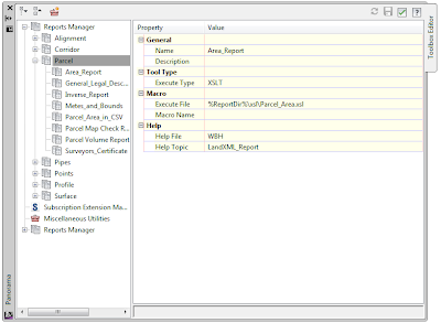
The report manager displayed below shows the reports, and also where the executable file to run the report exist. 


Notice if you click on a report heading, you can select the new tool option.  This allows the user to add an additional report.


After selecting the new tool, you will first need to give the name of the report we are going to add.


The next option to choose is the execute type.  This will depending on the report type.


Next, we simply need to choose the execute file that will run the report.


By picking the ellipse, the user will be allowed to add the appropriate file to run.  It's important to note that these report files typically reside in the following location:

C:\ProgramData\Autodesk\C3D 2013\enu\Data\Reports\xsl


Finally, we need to save the settings.


As you can see below, the report has been added, and now all we need to do is hit execute and use.




Wednesday, July 18, 2012

Part Parameter Error Fixed in Civil 3D 2012

For anyone who has made any custom changes to optional parts within a pipe catalog, the following is a familiar scene.


Autodesk recently released Civil 3D 2012 Update 2.  While looking through the list of issues that were resolved with this update, I came across the following:


In the past, this error occurred because the parameter wasn't configured properly, or most likely because the template containing the custom parameter was set in options to be QNEW.  In the past, I always told my clients that this was a benign error, and to simply hit OK.  Now with the update, the error is a thing of the past.  On a side note, you can not run an automatic removal of this update.  You will need to uninstall Civil 3D 2012 and re-install it.


Monday, July 16, 2012

Borehole Utility for Civil 3D 2012

From Autodesk Subscription, you have access to additional product enhancements.  One enhancement I chose to take a look at was the Borehole Utility, which is a part of the Civil 3D 2012 productivity tools.  This utility allows the user to import Borehole data into both plan and profile view. 


After loading the utility, here is what you should see on the toolbox tab of toolspace.


To run the utility, the user simply needs to right click on the Importer and select execute.


After running execute, you will see the following pop up.


The important things to note on the importer are as follows:

  1. Under file in folder, you will select the file to be imported.  Note that you can select a csv or ags file to import.
  2. The create Civil 3D points option must be checked on.
  3. Under surface, the user will be asked which surface they wish to tie the points to.  This surface will determine the top elevation from which the boring information will start from.  In the capture above, I imported a Google earth surface prior to the import.
  4. Under profile view, we need to select the profile profile view for which we want the boring information to be projected into.

The setting tab of the importer allows for the user to specify display options.  Most of the settings are self explanatory, but the two I will focus on are profile view settings and labels.  
  1. The profile view settings allows the user to determine an acceptable distance from a given alignment that is allowed to display boring data within the profile view.  If the boring point falls outside of the maximum distance, the boring will not be displayed with the profile view.  
  2. The labels settings simply allows the user to determine what labels will be displayed upon import into the profile view.  Sometimes the user may need to import multiple times to determine if the boring has too many or too few labels.


The screen capture above shows the boring data as Civil 3D points in plan view after they have been imported.


The screen capture above shows the boring data in profile view after they have been projected.  It is important to note that the projections are not dynamic, and will need to be re-imported if the boring locations change.  Also, the hatch patterns in the boring block, like the one above, are controlled by the same shape styles that dictate hatch patterns within subassemblies

Wednesday, July 11, 2012

Pressure Pipe Modification

As most of you have seen by now, Civil 3D 2013 has some functionality for creating pressure pipe.  While we are all used to editing various pipe and structure parameters in parts builder, pressure pipes have their own tool called Content Catalog Editor.  The Content Catalog Editor can be found in the following location:  

START-PROGRAMS-AUTODESK-AUTOCAD CIVIL 3D 2013-CONTENT CATALOG EDITOR


The screen capture below shows the content editor.


After selecting the editor, you will need to choose open and pick the appropriate sqlite file containing the pipe you want to modify.  These files will typically be found in the following location:

C-PROGRAM DATA-AUTODESK-C3D2013-ENU-PRESSURE PIPE CATALOG-IMPERIAL


After choosing the appropriate file, you will see the content editor populate as follows:


At this point, it is just a matter of selecting the appropriate field, modifying the parameter, and ultimately saving the file.


The next time you get into Civil 3D, the part will be modified and ready for use.


Thursday, July 5, 2012

Hiding Assemblies in Drawings


More improvements, in Civil 3D 2013, to assemblies and subassemblies include the ability to hiding them in drawing.  The command is hidden behind a right click after selecting the desired object, select “Remove from Modelspace

To bring them back into the drawing is as easy as right clicking on the assemblies and selecting “Insert to Modelspace

This new functionality can allow us to create empty templates with hidden parts.  As an odd note, you can create a corridor by making references to these hidden assemblies.